Understanding Network Devices
Search for a command to run...
No comments yet. Be the first to comment.
When we write CSS, our main goal is very simple: we want to apply styles to specific parts of our webpage. But how does CSS know which elements we are talking about? That is where CSS selectors come in. Selectors are the foundation of CSS. Without se...

When someone visits a website, they usually see colors, buttons, images, and animations. But underneath all of that, the real structure of every webpage is built using HTML. HTML is the starting point of web development.No matter how advanced a websi...

When you type a website like www.google.com into your browser, have you ever wondered how your computer knows where that website actually exists? After all, the internet does not understand human-friendly names. It only understands numbers called IP ...
Web Dev Cohort 2026
4 posts
When we use the internet, it often feels almost magical that everything we need is available within a few clicks. However, behind this apparent simplicity lies a highly complex system and an entire machinery working silently in the background. Even the most basic online action depends on a carefully coordinated interaction among multiple technologies that work together to deliver seamless connectivity.
At the foundation of the internet is a massive physical infrastructure responsible for moving data across the globe. This infrastructure, commonly referred to as the backbone of the internet, is made up of high-capacity fiber-optic cables and a wide range of networking devices such as routers, modems, switches, and hubs. In this article, we will explore these core internet components in detail and understand how they collectively power the digital experiences we rely on every day.

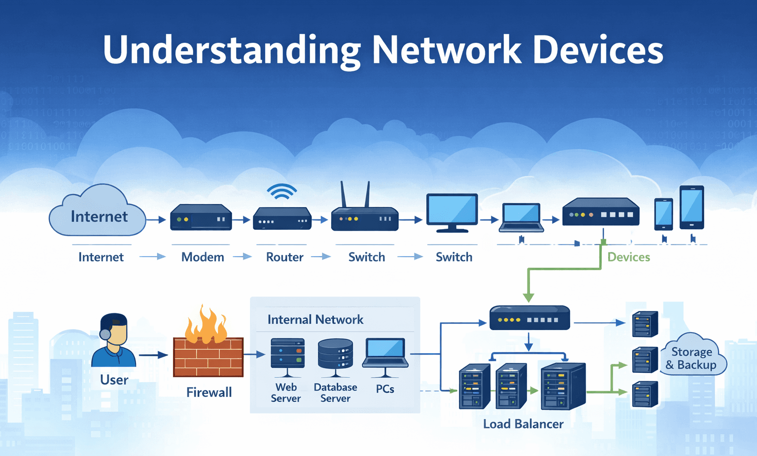
The term modem stands for Modulator–Demodulator. It is a fundamental networking device that connects your home or office network to your Internet Service Provider (ISP). In simple terms, the modem acts as the gateway between your private network and the public internet. Without a modem, your devices would have no way to communicate beyond the boundaries of your local network.
At a technical level, the modem’s primary responsibility is signal conversion. Your computer and router generate digital data, but this data cannot travel directly over the physical medium used by your ISP, such as fiber cables, coaxial lines, or telephone wires. The modem solves this problem by converting (modulating) your digital data into signals that can travel across the ISP’s infrastructure, and then converting (demodulating) incoming signals back into digital data that your devices can understand.
A helpful way to think about a modem is as a translator between two different languages. Your internal network speaks in pure digital terms, while your ISP’s network uses a different transmission format depending on the technology involved. The modem ensures that both sides can communicate smoothly, even though they operate using different signaling methods. In this sense, the modem truly represents the entry point of the internet into your network, silently enabling every website you load, message you send, and video you stream.
A router is a core networking device responsible for forwarding data packets between different networks. Its primary role is to determine the most appropriate path for data to travel so that it reaches the correct destination. In practical terms, the router allows multiple devices, such as laptops, smartphones, and smart TVs, to share a single internet connection efficiently and reliably.
At a structural level, a router connects two distinct network domains. On one side is your Local Area Network (LAN), which includes all the devices within your home or office. On the other side is the Wide Area Network (WAN), which represents the broader internet. The router sits between these two environments and manages the flow of traffic using a process known as routing, where each packet is inspected and forwarded based on its destination IP address.
If the modem can be thought of as a translator that brings internet signals into your network, then the router functions as a traffic controller for your digital environment. While the modem establishes the connection, the router decides which device should receive which data. Every video stream, file download, and online meeting depends on the router’s ability to intelligently distribute traffic across your network without collisions or confusion.
Once the router determines that a data packet belongs to your Local Area Network (LAN), the task of delivering that packet shifts to the devices responsible for building the internal network, namely the hub and the switch. At first glance, these devices look almost identical: small boxes with multiple Ethernet ports. However, despite their similar appearance, they operate using very different principles and offer drastically different levels of efficiency and intelligence.
A hub is a passive networking device that operates at the Physical Layer (Layer 1) of the OSI model. It has no awareness of the devices connected to it and does not store or analyze any addressing information. Essentially, a hub functions as a multi-port repeater. When it receives a data signal on one port, it simply broadcasts that signal to all other ports, regardless of the intended destination.
Because of this behavior, hubs create a single shared communication space. Every connected device sees all traffic, and only one device can successfully transmit data at a time. This leads to frequent collisions and significant performance limitations, which is why hubs are now considered obsolete in modern networks.
A switch is an active device that operates at the Data Link Layer (Layer 2) and introduces intelligence into the network. Unlike a hub, a switch understands which device is connected to which port. It does this by examining the MAC address, the unique physical identifier of each network interface.
Over time, the switch builds a dynamic internal database known as a MAC Address Table, which maps each MAC address to a specific port. When a data frame arrives, the switch consults this table and forwards the frame only to the port associated with the destination device.
This results in precision delivery. If Computer B is connected to Port 2, the switch sends the data directly to Port 2 and nowhere else. Other devices on the network never see this traffic. Each connection becomes isolated, allowing multiple conversations to occur simultaneously without interference.

This isolation technique is known as micro-segmentation. Each switch port becomes its own collision domain, enabling full-duplex communication, where devices can send and receive data at the same time. The result is higher performance, better security, and far more efficient use of network bandwidth.
A hub is like someone using a megaphone in a crowded room. If they want to tell Bob something, they shout his name, and everyone hears the message. While this happens, no one else can speak without causing chaos.
A switch, on the other hand, is like a private telephone system. If you want to talk to Bob, the system connects you directly to his line. Your conversation remains private, and at the same time, others can hold their own conversations without interruption.
Although hubs are rarely used today, understanding their behavior highlights an important concept in networking. On a hub-based network, packet sniffing is trivial, so that any device can see all traffic just by listening. On a switched network, however, devices only receive packets specifically addressed to them. This makes traffic analysis, debugging, and security auditing more controlled and significantly more complex.
For engineers, this distinction explains why modern network monitoring tools must rely on techniques such as port mirroring, network taps, or logging at higher layers rather than simple passive listening.
If the router is the traffic director, the Firewall is the border control agency. In a network architecture, "security lives here" because the firewall represents the decisive boundary between the Trusted Zone (your internal network) and the Untrusted Zone (the public internet).
It is a security system (which can be hardware, software, or both) that monitors and controls incoming and outgoing network traffic based on predetermined security rules.
At its simplest level, a firewall operates by strictly enforcing an Access Control List (ACL). It inspects the "header" of every data packet, specifically the 5-Tuple information, to determine whether to allow or drop the traffic.
The 5-Tuple consists of:
Source IP: Where is it coming from?
Destination IP: Where is it going?
Source Port: Which application sent it?
Destination Port: Which service is it trying to reach?
Protocol: Is it TCP, UDP, or ICMP?
The firewall enforces the security model known as "Default Deny." In a secure environment, the firewall is configured to block everything by default, and administrators manually "punch holes" (allow rules) only for necessary traffic.
Ingress Filtering (Incoming): Prevents external threat actors from initiating connections to your internal devices. For example, it may allow traffic on Port 443 (HTTPS) to enable secure web access for users, while blocking Port 3389 (RDP) to prevent unauthorized remote desktop access.
Egress Filtering (Outgoing): Often overlooked but critically important. If a server in your network becomes infected with malware, the firewall can stop it from “phoning home” to a Command and Control (C2) server by blocking unauthorized outbound connections.

A firewall can be best understood by thinking of it as a security checkpoint at an airport. Just as passengers are not allowed to proceed without a valid boarding pass and a confirmed gate, network traffic is only permitted if it is coming from an authorized source and is targeting an approved port. Even then, access is not guaranteed. Much like airport security inspects luggage, modern firewalls, especially Next-Generation Firewalls (NGFW), go a step further by performing Deep Packet Inspection (DPI). This means they do not merely check where the traffic is coming from, but also examine the actual data being transmitted to detect potential threats such as malware or malicious payloads.
In the initial phase of an application’s lifecycle, a single server is usually enough to manage incoming requests. However, as the number of users increases, that same server gradually turns into a performance bottleneck and a potential single point of failure. This is where the Load Balancer becomes an essential component of system architecture.
A Load Balancer is a piece of hardware or software that operates as a reverse proxy, intelligently distributing incoming traffic across multiple backend servers. Its primary purpose is to improve both the capacity of the system by supporting more concurrent users and its reliability, by ensuring the application remains available even if individual servers fail.

Scalability generally occurs through one of two approaches. The first is vertical scaling, where additional CPU, memory, or storage is added to a single machine. While this may work initially, it has clear physical limits and quickly becomes costly. The second approach is horizontal scaling, which involves adding more servers to handle the load. This method is far more flexible and practically unlimited, but it introduces an important question: how does the system decide which server should handle each incoming request?
The Load Balancer addresses this challenge directly. Positioned between users and the pool of servers, it ensures that traffic is evenly distributed so that no single server becomes overloaded, thereby maintaining consistent performance across the system.
A useful way to understand a Load Balancer is to compare it to a host at a busy restaurant. Without a host, customers might seat themselves randomly, leaving some waiters overwhelmed while others remain underutilized. The host solves this by managing the flow of guests, directing each person to a waiter who has available capacity. Similarly, a Load Balancer keeps track of which servers are free and which are busy, and routes requests accordingly. If one server goes offline, the Load Balancer simply stops sending traffic to it, ensuring that users experience little to no disruption.
To truly understand how networking components work together, it helps to follow a real-world scenario from start to finish. Consider a simple action: a user at home clicks the “Checkout” button on a popular e-commerce website. Behind this single click is a carefully coordinated journey that spans multiple layers of infrastructure, from the user’s local network to the company’s data center and back again. This journey connects the User’s Edge, the home network, with the Application’s Edge, the server infrastructure powering the website.
The process begins the moment the user clicks “Checkout.” The laptop sends the request to the home router, which identifies that the destination lies outside the local network. The router then applies Network Address Translation (NAT), replacing the private IP address with the home’s public IP, and forwards the packet toward the internet. The modem receives this digital signal and converts it into a format compatible with the internet service provider’s physical medium, such as fiber or coaxial cable, before sending it into the broader internet.
After traveling across multiple networks, the request reaches the company’s data center. The first components it encounters are the gateway and firewall, which act as the system’s security checkpoint. The firewall inspects the incoming traffic, verifying that it is using an allowed port (such as HTTPS on Port 443) and that the source is not flagged as malicious. Only after passing these checks is the request permitted to enter the internal network.
Since the website serves thousands or even millions of users, a single server cannot handle all the traffic. Instead, the request is routed to a load balancer. The load balancer evaluates the current state of all available backend servers and selects the one with the lowest load or best performance at that moment. It then forwards the request to that specific server, ensuring traffic is distributed efficiently and fairly.
Inside the data center, the request reaches a network switch. The switch reads the packet’s hardware address and forwards it only to the correct physical server, rather than broadcasting it across the entire network. This targeted delivery ensures high-speed communication without unnecessary network congestion.
The selected server processes the request by executing backend logic, interacting with databases, and generating a response. Once the task is complete, the response travels back through the same chain in reverse—through the switch, load balancer, firewall, internet, modem, router, and finally back to the user’s device, where the confirmation appears on the screen.
